How it works
The FireFly is a key activated, fully automatic well ignition system. The control panels for our system have a built in variable time delay and are usually located at the primary briefing areas. This ensures that members of the ignition team have sufficient time to evacuate the affected area. Due to the integrated time delay, egress occurs before the ignition process begins. The FireFly Well Ignition System will continue to discharge at preset intervals to SUSTAIN ignition with no need for personnel to re-enter the location. Unlike a flare gun, the gel stream discharged from the FireFly unit creates Multiple Ignition Points to ensure immediate ignition.
Utilization of a FireFly Well Ignition System on gas and oil wells exceeds minimum safety standards and demonstrates a commitment to safety for residents, workers and infrastructure in the Emergency Planning Zone.
Firefly advantages
FireFly has refined its ignition systems over its 30 years in business and has designed its systems to provide a straightforward and reliable approach.
- 30 Years of Well Ignition Experience - Our system has been used in real world well control events as well as many field testing exercises. We have perfected the design of our system to ensure the safest, most reliable ignition solution for our customers.
- Proprietary FireFly HG Gel Product - FireFly’s flammable gel product is the best in the business! The viscous gel product creates a smooth, high angle discharge that promotes ignition throughout the firing sequence. Upon reaching the top of its trajectory, the gel stream breaks up and creates Multiple Ignition Points that will encourage ignition. On today’s large rigs, it is critical to be able to elevate the ignition stream to a level where an adequate air/fuel mixture will be present. Failure to ignite the exiting gas stream at the appropriate air/fuel mixture may delay or compromise the contingency plan. The gel product has a residual burn time of several minutes ensuring that an ignition source will be present on location at all times throughout the ignition sequence.
Our design has been perfected to provide and ensure the safest, most reliable ignition solution for our customers
LARGE 250 LITER DISCHARGE RESERVOIR
The FireFly Well Ignition System utilizes a large reservoir that contains our FireFly HG product. It has the ability to sustain ignition for an extended period of time. During a blowout, it is possible that environmental conditions may be such that re-entry to a lease is not possible. If this is the case, the best option is to sustain ignition for as long as possible to ensure the safety of those in the EPZ.
Top Mount Discharge Canon
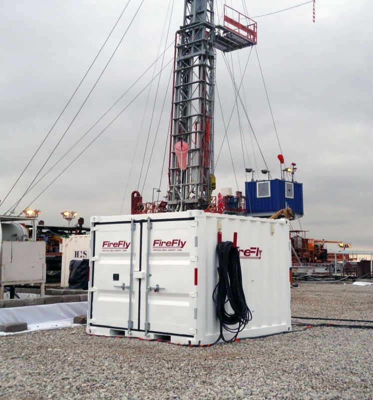
The versatile canon provided by FireFly allows flexible placement on locations where lease space may be limited. The discharge canon has the ability to be rotated 180 degrees to ensure a clear line of site to the target. In some instances, the system may need to be placed adjacent to another container on site. In these instances, the adjustability of our top mount canon will be required to provide an effective discharge trajectory to achieve ignition.
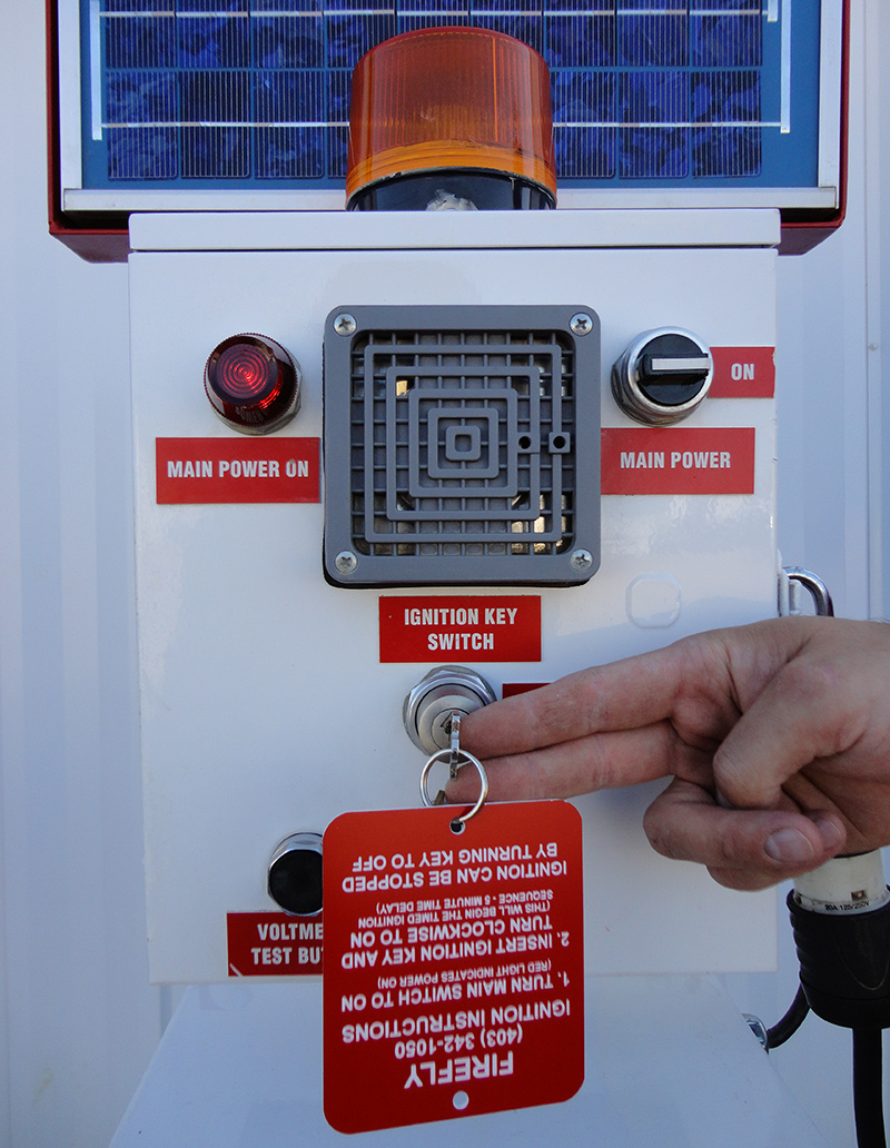
Safe Electrical Design
The FireFly Well Ignition System employs many safety features in its electrical design:
- 12 volt DC system The power source. All power sources are located at the remote control panels with no power to the system until later stages in the egress period.
- If the FireFly System is struck or damaged in any way during rig operations, the system is designed to be unable to discharge or malfunction. The interconnecting cable between the FireFly and the control panel is not energized until the moment of ignition.
- Should transient vapours be produced during drilling operations, there will be no possibility for a spark to be generated within the well ignition system.
- The system contains a solar backup to maintain the battery packs for extended service life on long jobs.
- A three-stage ignition sequence ensures adequate time for all personal to evacuate the affected area prior to the moment of ignition.
- The ignition sequence can be stopped at any stage throughout the egress period.